Originally built by I4BBO (Valentino Barbi).
This device was inspired by Geloso G.4/214 and G.4/216.
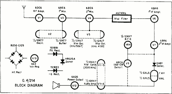
HERE is the block diagram of the G.4/214.
It does not completely follow the schematics of either, though.
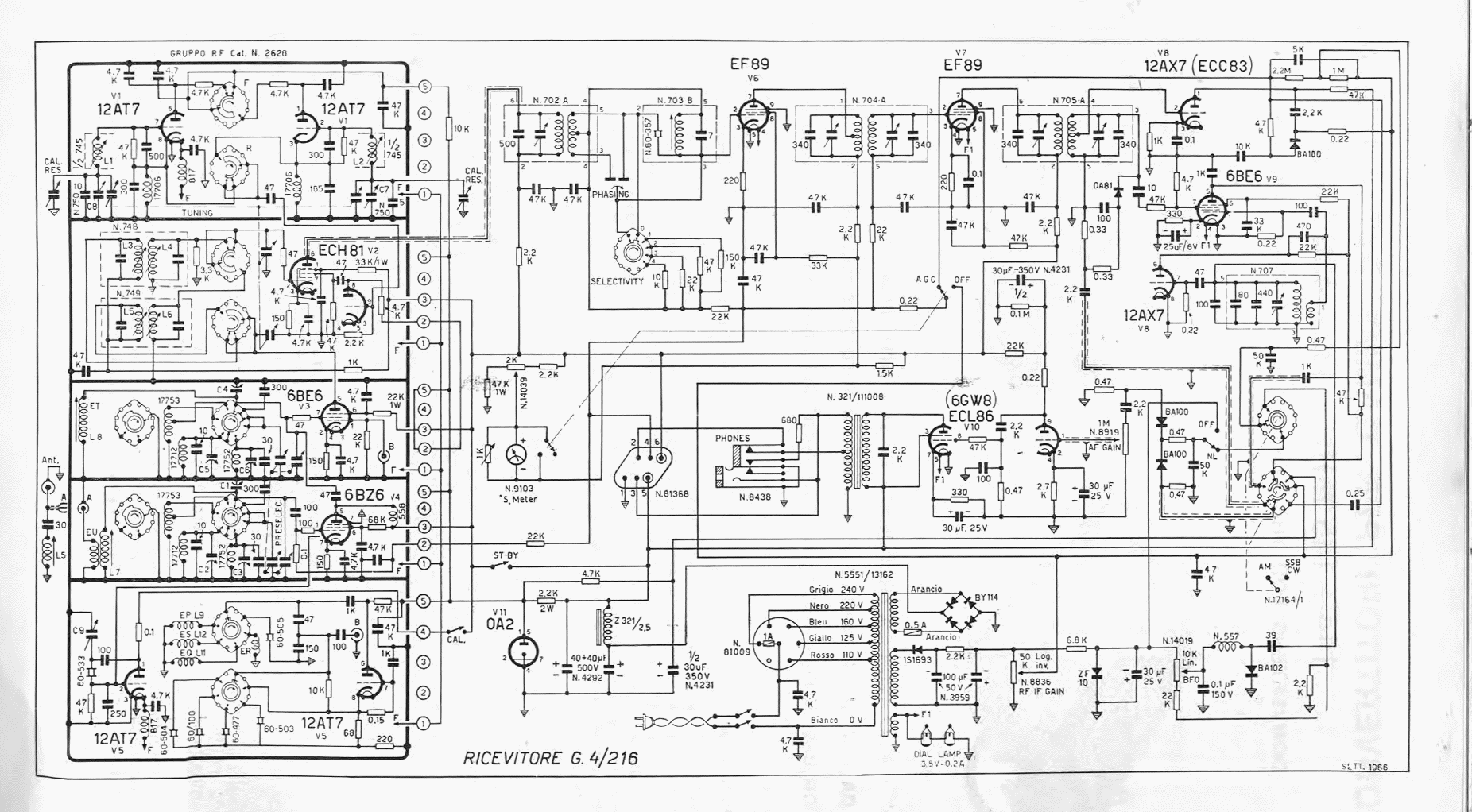
Some notes HERE about the G.4/216 (italian).
You can see a map of the top of the chassis here. The picture also contains a partial mapping of the components to the G.4/214 schematics.
Mapping of the tubes between the Geloso G.4/214 schematics and the homebrew receiver.
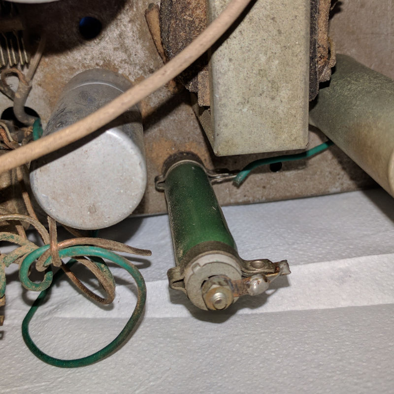
The transformer is toast, has clear signs of scorching.
Warning: All the voltages here are calculated after rectification.
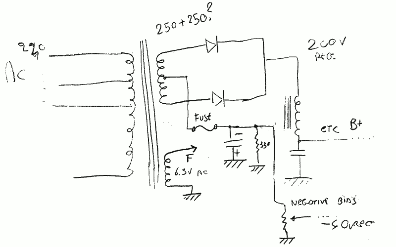
Supposedly, the transformer in the homebrew RX is using two windings: a 500v winding with a center tap (or two 250 windings joined together) and a 6.3v winding for the filaments. The design is using back-biasing.
A schematic of the probable configuration can be seen HERE.
We should obtain:
A rough calculation of current for the windings is:
Rough sizes for the transformer are 9x8x8 (in cm).
We need to take into account that when rectifying AC, the DC voltage will be around 1.41 of the value. A good substitute would be using a 190-0-190 and using multiple taps on the primary.
The mains tension selector (110/240) is toast. Its input is not conducting to the primary winding of the transformer.
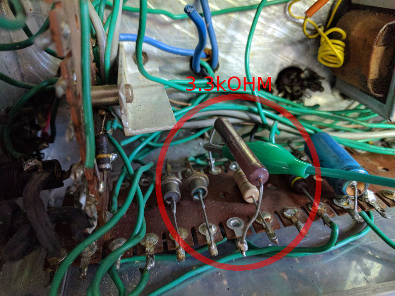
The OA2 circuit uses a 3.3kOHM resistor as limiter in place of a 2k. Also, the filter caps are made by a 32uF+32uF double cap in place of a 50uF+50uF.
OA2 stabilizes at 150V, nominal. The voltage that must be applied to start the process is around 15 to 20% of the desired regulated voltage. A resistor is used to limit the current flowing through the tube. Current in operating conditions is between 5 to 30mA.
Hopefully I understood how to calculate the resistor for current limiting on the VR tube... Suppose we want a current of 15mA, we have an input of 200v, and we want to regulate it to 150 with an OA2. We need to calculate Vdiff = 200 - 150 = 50v. We want 15mA at 50v drop:
R=V/I
50V / 0,015A ~= 3.3kOHM.
See notes here.
RF IF gain circuit is slightly different and is protected by a fuse (which is blown and was bridged). See a drawing of the difference here.
See above for possible transformer circuit.
Geloso's Bollettino number 85 states (page 22) that the negative polarization required for the grids ranges from 0 to -40v, set by a potentiometer. See Pin 1 of the third group on the R.F. module.
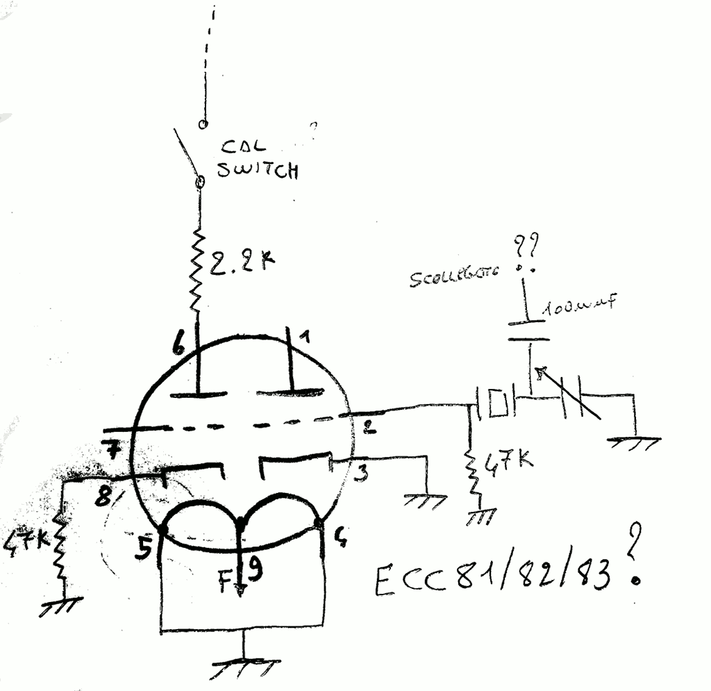
Possibly an ECC81/ECC82/ECC83.
Possibly a 3500khz crystal.
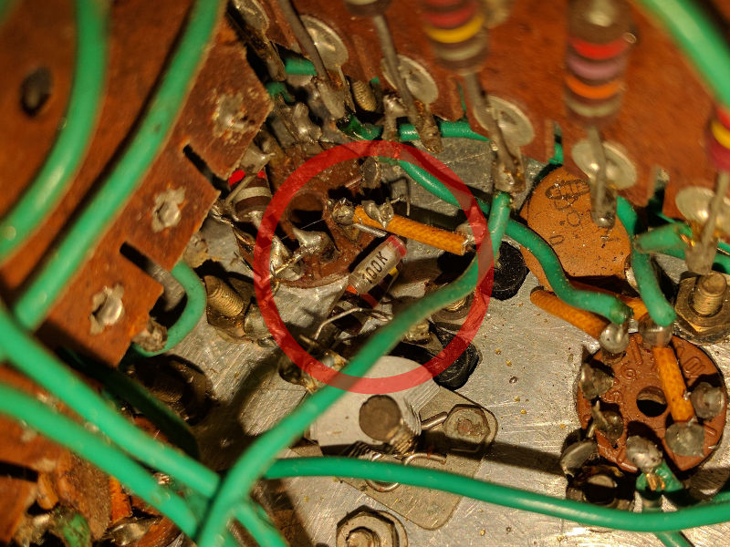
The calibration circuit valve has a disconnected capacitor on the socket. This capacitor (100pF?) might have been connected on pin 1 or on pin 6, to the anodes of the tube. Have yet to check.
Calibration circuit for the receiver is sensibly different from the one in G.4/214. See HERE for a drawing of the circuit.
The circuit might be incomplete and/or non-working.
Geloso G.4/214 uses a double triode to perform 2nd IF conversion (using a 5067Khz or a 4133Khz crystal depending on which sideband is selected). This homebrew receiver has no 4133Khz crystal, and just a 5067Khz one is present in circuit. Also, it is NOT installed on a N.708B transformer. As there is no selector for LSB/USB, probably the receiver supports only one of the modes, removing the need for two crystals. Possibly, the oscillator for the 5067Khz crystal uses the triode half of ECH81. TO BE VERIFIED.
Possibly a 6BA6.
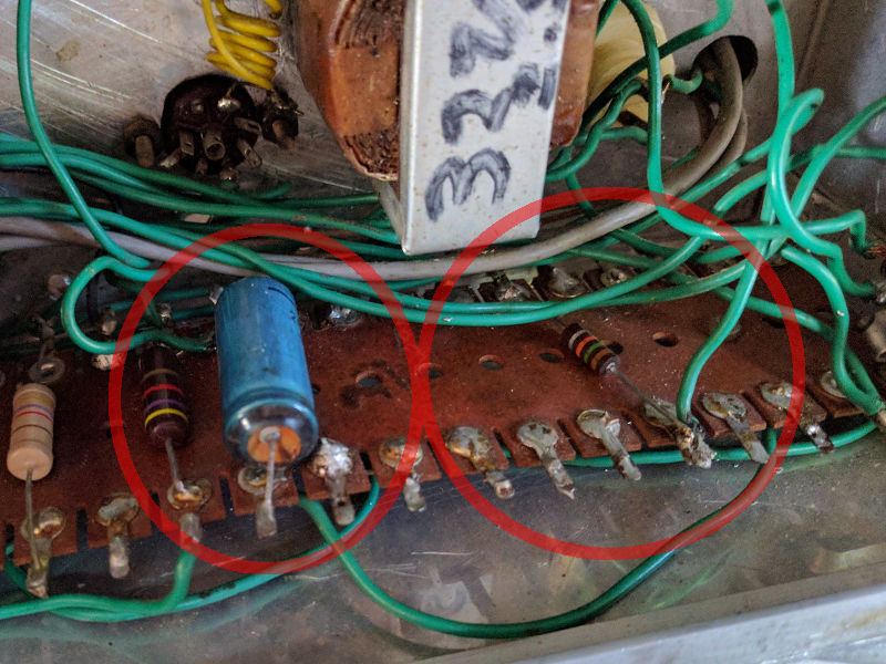
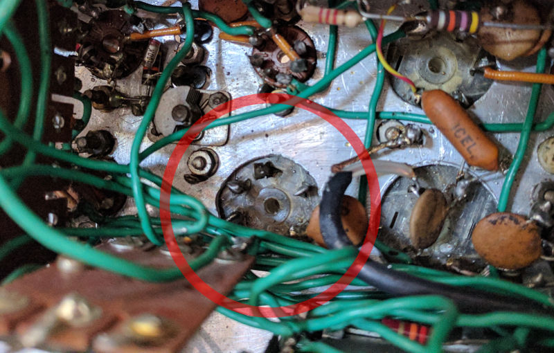
One of the shielded transformers is completely disconnected, save for one pin, connected to a capacitor. See the photo. Maybe unused?
The shielded transformer marked as N705B has one end of a wire connected to pin 3. The other end of the wire is not connected to anything. Apparently the circuit is connected correctly and the wire serves no function (maybe a leftover?).
The ANL switch on the front panel is completely disconnected from anything. Also, pin 4 of N705B should be connected to the ANL circuit, but is disconnected. The ANL circuit seems completely missing.
Back to Menu